System Overview
External Panels and Controls
Front Panel
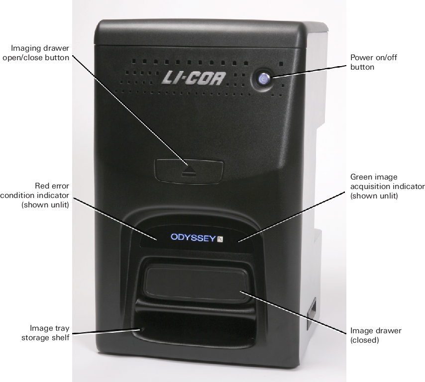
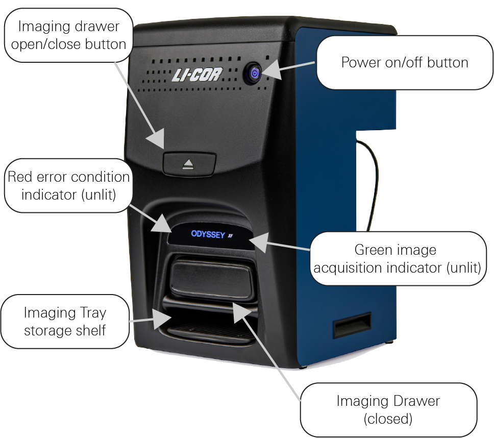
Power On/Off Button: Pressing this button momentarily turns the instrument on and off. While the instrument is performing its startup or shutdown procedure, the blue indicator light in the power button blinks. When the blue indicator light is continuously on, the instrument is ready for operation. Pressing the power on/off button when the green image acquisition indicator is lit will cause the red error condition indicator to illuminate. This is just a warning that the instrument is in use.
Green Image Acquisition Indicator: This indicator light blinks during image acquisition and is continuously on at other times, as long as communication with Image Studio™ SoftwareLI‑COR® Acquisition Software


Red Error Indicator: The error indicator light illuminates when a particular process could not be completed. If the imaging drawer button is pressed before an acquisition is complete, for example, the error indicator illuminates. See Image Studio™ SoftwareLI‑COR® Acquisition Software
Imaging Drawer Button: This button opens and closes the imaging drawer in normal operation. The drawer front can be used to open or close the drawer in cases of power loss. Pressing the Imaging Drawer button when the green image acquisition indicator is lit will cause the red error condition indicator to illuminate. This is just a warning that the instrument is in use.
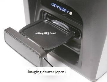
Imaging Drawer: The imaging drawer moves the imaging tray into position under the camera for imaging. The bottom of the imaging tray has a marker in each corner that indicates the edge of the camera’s field of view.
Right-side and Rear Panels
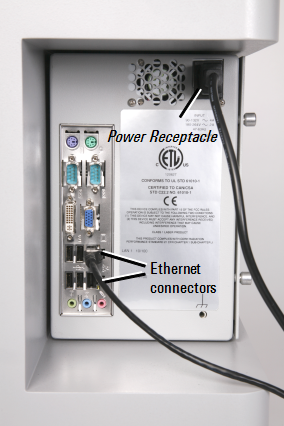 | 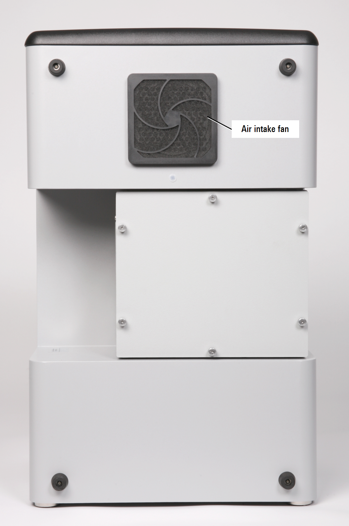 |
Note: The appearance of your instrument's back panel may vary slightly from the one shown. |
Optical System Description
The Odyssey XF Imager is designed to image Western blots, membranes, or gels using visible, near-infrared or chemiluminescent methods. Before image acquisition starts, the imaging tray containing a membrane or gel is placed in the Odyssey XF imaging drawer and the drawer is closed. A safety interlock prevents operation of the laser illumination module while the imaging drawer is open. Image acquisition is started via your acquisition software.
The Odyssey XF Imager has four detection channels: two are infrared channels with 685 and 785 nm lasers, one is a 600 nm channel with a light source for excitation, and the fourth is for detecting visible wavelength emissions from chemiluminescent substrates. The channels used during acquisition are chosen in your image acquisition software.
The Odyssey® XF Imager laser module contains a 685 nm and 785 nm laser. During image acquisition, each laser source is turned on, followed by image acquisition with the LI‑COR® CCD camera. For infrared imaging, a typical image acquisition consists of images for two fluorescent probes in the 700 and 800 nm channels (assuming both channels are enabled). Image acquisitions from chemiluminescent substrates use just the chemiluminescence channel and imaging is done at visible wavelengths. Note, however, that fluorescent markers can be imaged separately in the 700 nm channel and combined with the image from the chemiluminescence channel. Coomassie stains can also be imaged in the 700 nm channel. DNA gels stained with ethidium bromide or other comparable stains (such as SYBR Safe) can be imaged in the 600 nm channel.
The quality of images from the Odyssey XF Imager is enhanced by a patented filtering system that dramatically reduces noise before detection by the CCD detector. Infrared signal detection has also been optimized for LI‑COR® IRDye® near-infrared dyes, which eliminates the need for filter selection by the user before imaging. The unique imaging technology, FieldBriteTM XT, used in the Odyssey XF Imager acquires images without saturated pixels on the first attempt with no user adjustments. More than six logs (22 bits) of dynamic range are available for each image.
Imaging Drawer
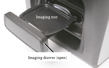
The imaging drawer is opened and closed by pressing the large button above the drawer (see Figure 73. ).
Imaging Drawer Safety
Be careful not to get your fingers caught between the Odyssey XF Imager and the imaging drawer when the drawer closes. The drawer is specially designed to stop when a certain level of resistance is detected, so no harm should result, but the experience may be startling.
During an unexpected power loss, the drawer button will not function. This may leave a sample inside the Odyssey XF Imager, or it may result in the imaging drawer being left partially open or closed. If the power remains off, the drawer can be opened or closed by pulling or pushing on the drawer front. The imaging drawer should resume normal operation once power is restored.
Sample Placement
The Odyssey® XF Imaging Tray has four corner markers that delineate the edges of the Odyssey XF imaging area. Place membranes or gels up to 10 x 12 cm on the imaging tray within the corner markers for the entire membrane or gel to be imaged.
The imaging tray is designed to contain the small volume of liquid needed to keep blots or gels moist. Do not fill the imaging tray and be careful not to add so much liquid that the sloshing action created by closing the drawer may result in a spill inside the instrument.
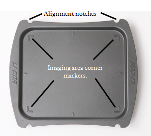
Place membranes sample-side up with the top toward the rear of the imager.
Place gels sample-side up with the top toward the rear of the imager.
Trays can be cleaned (Clean Tray), but they should be discarded if an unacceptable amount of residual signal remains on the tray after cleaning. Trays can be reordered using P/N 926-40020 (5pk).
Insert Imaging Tray into Drawer
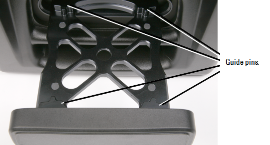
The imaging tray is inserted in the imaging drawer by aligning the notches in the tray with the guide pins in the imaging drawer (Figure 79), and lowering the tray into the drawer. Make sure the tray rests flat on the imaging drawer before pressing the open/close button to close the drawer.
Clean Tray
Trays may be discarded after use. Trays should be discarded if they are damaged or if an unacceptable level of residual signal remains after cleaning.
The following procedure may allow you to clean the tray sufficiently for reuse. If you choose to reuse the tray, it should be cleaned before and after each use.
Remove sample from tray.
Always handle membranes with forceps.
Clean tray with water and wipe with a lint-free wipe.
Do not use blue wipes.
Rinse with 70% ethanol or 70% isopropanol and lint-free wipes. Methanol may be used if necessary.
Do not use acetone or any other harsh solvents to clean the imaging tray.
Sticking Imaging Drawer
If the Odyssey XF imaging drawer does not open and close smoothly, contact LI‑COR technical support for instructions about acquiring the correct lubricant and correctly applying the lubricant.